TTL output uses differential wiring (A with /A and B with /B) to cancel noise.īecause TTL output encoders always use differential (complementary) signals, they’re sometimes referred to as “differential line drivers” or “balanced differential line drivers,” and are compliant with the RS422 standard when operated with a 5 VDC supply. When the output is in the logic “low” state, the output signal is 0 VDC. Incremental encoders with transistor-transistor logic (TTL) output provide a 5 VDC signal when the output is in the logic “high” state, regardless of the supply voltage, which can range from 4.5 to 5 VDC or from 10 to 30 VDC. These encoders are often used when the controller requires a 12 or 24 V signal for the feedback input, or when the input voltage to the encoder is variable. The supply voltage for HTL output encoders can range from 10 to 30 VDC, with 24 VDC being common. A sourcing device provides power and “pushes” the current through the load. A sinking device provides a path for the current to ground and does not provide power to the device. Sinking and sourcing are terms that refer to the direction that current flows when one signal is activating another signal. This is why HTL output is sometimes referred to as “push-pull” output. When the output is off, or in the logic “low” state, the output voltage equals the supply common voltage level, in effect “pulling” or “sinking” the output signal from the load.

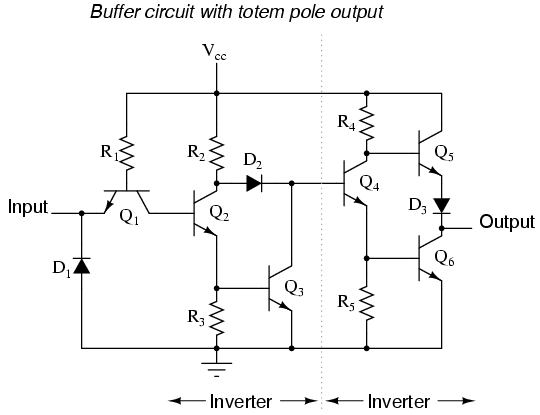
When the output is active, in the logic “high” state, the output voltage equals the supply voltage, so the transistors are “pushing” or “sourcing” the output signal to the load. Incremental encoders with high transistor logic (HTL) output generate the output signal using two transistors in a totem-pole configuration.

Incremental encoders can provide any of several types of digital output signals, but the two most common are high transistor logic (HTL) and and transistor-transistor logic (TTL).

Incremental encoders for digital output signals Those that produce digital output signals are typically referred to as simply “incremental encoders,” while those that produce analog output signals are referred to as “sine-cosine encoders.” These output signals can be in the form of analog sine and cosine waves or in the form of digital square waves. Encoders that provide incremental position measurements (whether rotary or linear) output two signals, or channels, typically termed “A” and “B,” to provide position and direction information.


 0 kommentar(er)
